ERITECH System 3000 Lightning Protection System
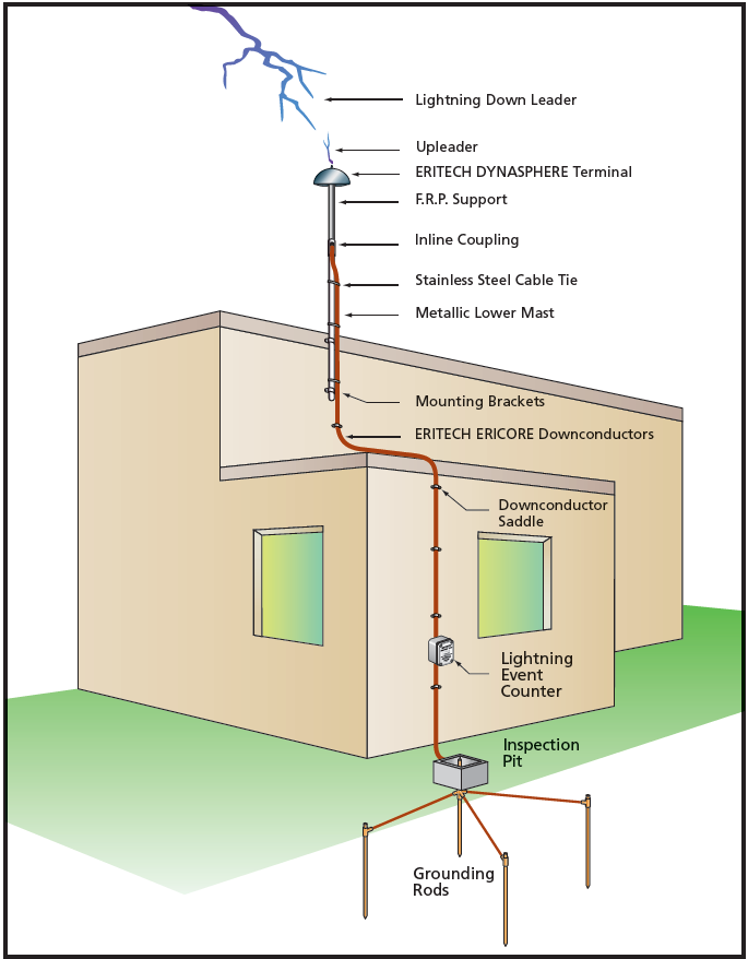
The ERITECH® SYSTEM 3000 is a technically advanced lightning protection system.
The unique features of this system allow the achievement of reliable lightning capture and control.
The ERITECH® DYNASPHERE air terminal provides a preferred point for lightning discharges which would otherwise strike and damage an unprotected structure and/or its contents. The ERITECH® DYNASPHERE is optimally connected to an ERITECH® ERICORE down conductor and low impedance grounding system in such a way as to provide a totally integrated system.
ERITECH SYSTEM 3000 includes the following elements:
• ERITECH® DYNASPHERE air terminal
• ERITECH® ERICORE down conductor
• Lightning event counter
• Purpose designed low impedance grounding system.
These components form an integral part of the ERICO® Six Point Plan of Protection.
Each component must be considered independently and ultimately integrated together to form the complete lightning protection solution, as without such holistic approach to integration, there is limited protection.
While it is possible to implement a hybrid system using other components, it is important to realize that inefficiencies in any substitute represents an inefficiency in the protection system as a whole.
DYNASPHERE AIR TERMINAL
The primary function of an air terminal, or air termination system, is to capture the lightning strike to a preferred point, so that the discharge current can be directed via a down conductor system for dissipation into the grounding system.
For more than 200 years, little improvement was made in lightning protection systems.
However, modern research and recording methods have led to an improved understanding of the lightning discharge process, and various advancements have been achieved in the simulation of lightning electric-field conditions. Two fundamental concepts have emerged from these advancements in the lightning attachment process and air terminal performance:
• Air terminals that produce copious quantities of corona (space charge) are less efficient strike receptors.
• An optimum air terminal is one which launches an upward streamer when the ambient electric field is at a level to support the continual propagation of the leader.
The ERITECH DYNASPHERE has been developed with these two concepts in mind.
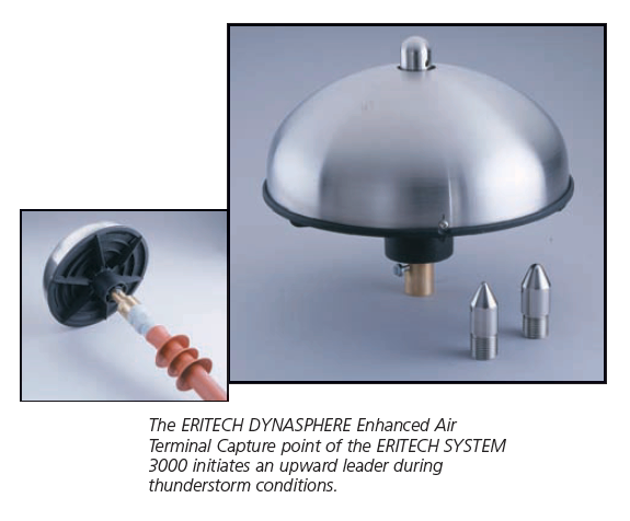
The ERITECH DYNASPHERE is an enhanced Franklin rod with a semi-spherical dome which is capacitively coupled to the electric field of an approaching lightning downleader. This spherical conductive dome surrounds a central earthed lightning rod.
The dome is insulated from the rod but connected to ground via a dynamic variable impedance with DC conduction.
The ERITECH DYNASPHERE is isolated from the structure using an insulated support mast. The mast also helps enable the safe connection of the ERITECH® ERICORE downconductor to the air terminal.
ERICORE DOWNCONDUCTOR
The function of a down conductor is to provide a low impedance path from the air termination to the ground system so that the lightning current can be conducted to earth, without the development of excessively large voltages.
In order to reduce the possibility of dangerous sparking (side-flashing), the down conductor route(s) should be as direct as possible with no sharp bends or stress points where the inductance, and hence impedance, is increased under impulse conditions
ERITECH ERICORE is a specialised coaxially screened and insulated downconductor that conveys higher frequency lightning current to ground safely via a known low impedance route, and in such a way as to ensure only minimal risk of sideflashing.
The unique ability of ERITECH ERICORE to confine discharge current and simultaneously support electrical bonding, helps ensure minimal risk to building, occupants and sensitive electronics.
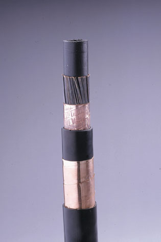
The design of the ERICORE cable is based on the use of coaxial cable theory and extensive laboratory testing using ERICO’s own High Voltage and High Current Impulse Generators here in Hobart Australia and Solon USA , as well as similar equipment at other high voltage laboratories elsewhere in the world.
In the design of the cable, ERICO had analysed both the electric field stress and the voltage stress that the cable will be subjected to under a variety of different conditions. Where ERICO had to use lightning related parameters as part of their analysis, they had extracted this information from Annex A of International Standard IEC 61204‑1, Protection of Structures Against Lightning.
Based on ERICOs measurements, and on the electrical parameters of the materials used in the manufacture of the conductor , ERICORE was able to withstand voltage impulses of over 200kV, and electric field stresses of over 100kV/mm for the main insulator.
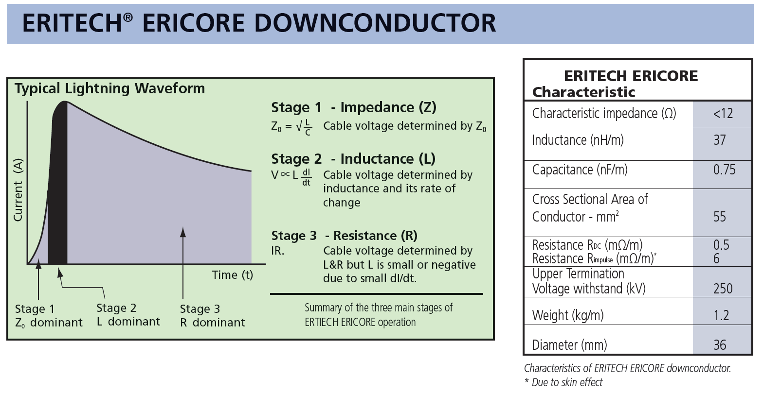
ERICO had also analysed the performance of the ERICORE cable by looking in turn at each of the three different stages of operation that occur during a typical lightning strike:
Stage 1: Impedance dominated mode
As the current begins to flow down the central conductor, a voltage is developed between it and the outer screen. The magnitude of this voltage is determined purely by the characteristic impedance, Zo, of the down-conductor and the magnitude of the applied current. This situation persists until the EM wave has travelled the round trip from the top of the cable to the short circuit at the bottom and returning up the cable screen.
Stage 2: Inductance dominated mode
The second stage is defined as the period immediately following the return of the EM wave to the cable top, where there is a transition to fully developed electromagnetic effects. The short circuit reflection results in a damping of the impedance effect and a transition to an inductive mode of operation. Now the voltage across the cable is determined by the inductance per unit length of cable and the dI/dt of the impulse. It is during this stage that the voltage developed at the upper termination of the cable is at its highest.
Stage 3: Conduction mode
As time progresses beyond Stage 2, the cable enters a time dependent conduction mode. The conduction current increases and the overall voltage developed across the cable decreases rapidly. Similarly, the rate of rise of current from the lightning impulse drops to low or even negative values.
Hence, this stage of down- conductor operation is unlikely to cause insulation failure because the voltages developed are several orders of magnitude lower than Stages 1 & 2 where the voltage measured at the top of the cable is roughly proportional to IR.
From their analysis, it is during Stage 2 that the voltage stresses on the cable are at their highest. Thus, in order to assess the likelihood of failure of the cable, ERICO had analyzed its performance in detail during this stage for different lengths and for different lightning currents.
What they found from this analysis is that for all but very long lengths of cable (75 mtr +) that ERICORE will not fail even under even the most extreme lightning conditions.
The ERITECH® ERICORE downconductors have been designed to meet criteria for an effective and reliable downconductor, with the following key characteristics:
• low inductance per unit length
• low surge impedance
• carefully controlled internal electric field distribution
Ensuring the conductor is well suted to handling the higher frequency components of high rise time currents typical of a lightning strike.
ERITECH® ERICORE offers purpose-designed performance in each phase of the lightning control process to help convey the energy safely to the grounding system.
As an example, consider the following comparison between the same 50 m length of conventional downconductor (25 mm x 3 mm copper tape) and ERITECH ERICORE downconductor, using the air breakdown electric field (nominally 3 MV/m) and cable termination voltage (250 kV) as the criterion for “failure” of the downconductors.
The conventional downconductor will, conservatively, cause a flashover or structure dielectric breakdown when carrying lightning currents of only ~ 30 kA. On the other hand, the ERITECH ERICORE screened/insulated downconductor can easily handle far greater lightning currents. This magnitude of lightning current is exceeded in only ~ 5% of lightning events or approximately once every 30 years in a region with a ground flash density of 5 strikes/km2/yr (approximately 80 thunder days/yr).
Main Benefits
- Lightning current is contained within the conductor where the semi conductive outer sheath is electrostatically bonded (albeit at high resistance) to the structure via metallic saddles thereby reducing the risk of sideflash.
- The low characteristic impedance of the cable minimizes internal dielectric failure.
- The cable is able to be routed away from sensitive equipment, electrical wiring, structural steel and human work areas.
- Allows the use of a single downconductor as opposed to multiple downconductors.
- Ease of installation.
- Minimal maintenance
THE GROUNDING SYSTEM
The grounding system must have a low impedance to disperse the energy of the lightning strike. Because the lightning discharge consists of high frequency components, we are particularly concerned with the frequency-dependent electrical parameter of a grounding system – impedance – as well as low resistance grounding.
Grounding systems are highly variable from site to site due to geographical considerations. The grounding grid should minimize the ground voltage potential rise and minimize the risk of injury to personnel or damage to equipment.
Design Considerations
Like any Lightning Protection System, the System 3000 needs to be designed to suit the particular use and application
Considerations such as the physical height , width, and depth of a structure, need to be considered along with the proposed down conductor route, as well as the location of the grounding system not being in close proximity to where humans may be exposed to the associated ground potential rise in any event where the LPS was struck.
The System 3000 LPS offers end users a simple and effective means to protect structures using a ” protection by isolation , where lightning strikes are attracted to a preferred point, where current can then be safely routed around sensitive areas where the current can then be directed into a low impedance earth termination, well away from areas where persons may traffic or congregate.
Contact Lightningman for Application Guidance and Design Assistance
-
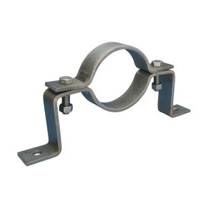
7000250S4 Galvanized Bracket
-
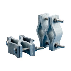
ACF2GS Mast Bracket X Shape
-

ALOF1GS Mast Support
-
ALUM3M 3 Mtr Alum Mast
-

ALUM4M 4 Mtr Alum Mast
-

ALUM5M 5 Mtr Alum Mast
-

ALUM6M 6 Mtr Alum Mast
-
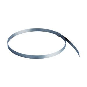
CABTIES Stainless Steel cable ties
-

CONSAD25 Conductive Saddles
-
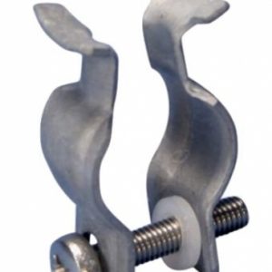
CR37-2 cable adaptor to suit Ericore conductor
-
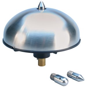
D/SMKIVSS Dynasphere Air terminal
-
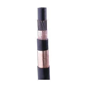
ERICORE Coaxial Downconductor
-
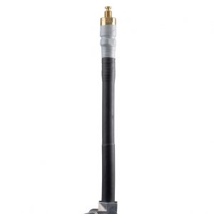
ERICORE Factory Termination Upper
-
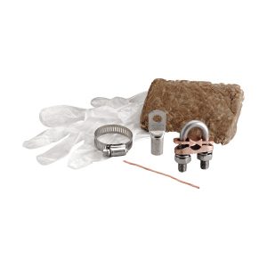
ERICORE LT/Kit Termination Lower
-
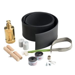
ERICORE Upper Termination Kit
-
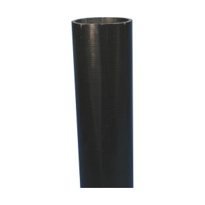
FRP2MBlack Fibreglass Mast
-

FRP4.6MBlack Fibreglass Mast
-

GuyKit10M/Grip
-

GuyKit12M/Grip
-

GuyKit17M/Grip
-

GuyKit4M/Grip
-

GuyKit7M/Grip
-
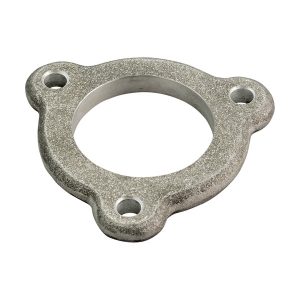
GUYRING
-
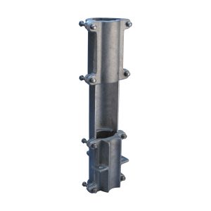
ILCOUPL Inline Coupling
-

ISOADNINTCPT ISODC S3000 TERMINAL ADAPTOR
-
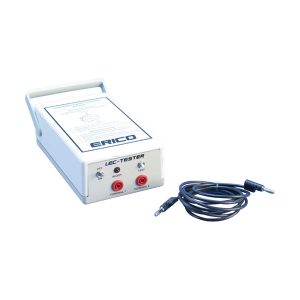
LEC Tester
-
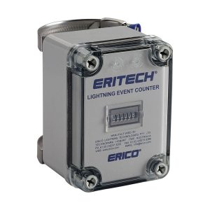
LEC-IV Lightning Event Counter
-
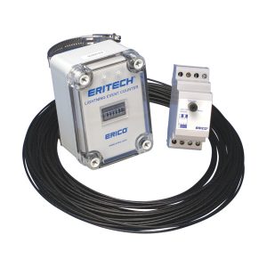
LEC-IVR Lightning Event Counter with remote monitoring
-
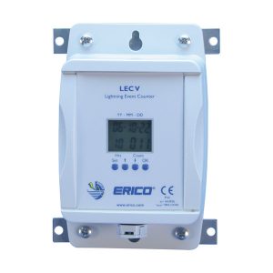
LEC-V Digital Lightning Event Counter
-
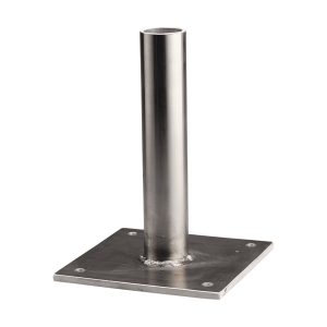
MBFRP4.6M – Mast base for 4.6M FRP
-
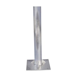
MBMAST4M – 4mtr Alum Mast with base
-

MBMAST5M – 5mtr Alum Mast with base
-

MBMAST6M – 6mtr Alum Mast with base
-
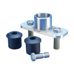
TERMDUALCOUP- Adaptor terminal to Dual Ericore and FRP
-
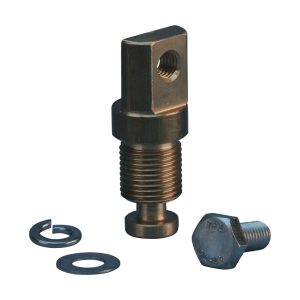
TERMLUGCOUP- Terminal Adaptor
-
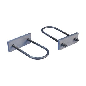
U Bolt Set
